|
Motor de Búsqueda de Datasheet de Componentes Electrónicos |
|
|
Motor de Búsqueda de Datasheet de Componentes Electrónicos |
|
CC1150-RTR1 Datasheet(PDF) 42 Page - Texas Instruments |
|
|
|||||||||||||||||||||||||||||
CC1150-RTR1 Datasheet(HTML) 42 Page - Texas Instruments |
|
|
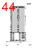
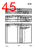
42 / 67 page  CC1150 SWRS037A Page 42 of 60 25 Configuration Registers The configuration of CC1150 is done by programming 8-bit registers. The configuration data based on selected system parameters are most easily found by using the SmartRF Studio [11] software. Complete descriptions of the registers are given in the following tables. After chip reset, all the registers have default values as shown in the tables. The optimum register setting might differ from the default value. After a reset, all registers that shall be different from the default value therefore needs to be programmed through the SPI interface. There are 9 Command Strobe Registers, listed in Table 25 Accessing these registers will initiate the change of an internal state or mode. There are 29 normal 8-bit Configuration Registers, listed in Table 26. Many of these registers are for test purposes only, and need not be written for normal operation of CC1150. There are also 6 Status registers, which are listed in Table 27. These registers, which are read-only, contain information about the status of CC1150. The TX FIFO is accessed through one 8-bit register. Only write operations are allowed to the TX FIFO. During the address transfer and while writing to a register or the TX FIFO, a status byte is returned. This status byte is described in Table 16 on page.20. Table 28 summarizes the SPI address space. Registers that are only defined on the CC1101 transceiver are also listed. CC1101 and CC1150 are register compatible, but registers and fields only implemented in the transceiver always contain 0 in CC1150. The address to use is given by adding the base address to the left and the burst and read/write bits on the top. Note that the burst bit has different meaning for base addresses above and below 0x2F. Address Strobe Name Description 0x30 SRES Reset chip. 0x31 SFSTXON Enable and calibrate frequency synthesizer (if MCSM0.FS_AUTOCAL=1). 0x32 SXOFF Turn off crystal oscillator. 0x33 SCAL Calibrate frequency synthesizer and turn it off (enables quick start). SCAL can be strobed in IDLE state without setting manual calibration mode (MCSM0.FS_AUTOCAL=0) 0x35 STX Enable TX. Perform calibration first if MCSM0.FS_AUTOCAL=1. 0x36 SIDLE Exit TX and turn off frequency synthesizer. 0x39 SPWD Enter power down mode when CSn goes high. 0x3B SFTX Flush the TX FIFO buffer. 0x3D SNOP No operation. May be used to pad strobe commands to two bytes for simpler software. Table 25: Command Strobes |
|
Enlace URL |
| ¿ALLDATASHEET es útil para Ud.? [ DONATE ] |
Todo acerca de Alldatasheet | Publicidad | Contáctenos | Política de Privacidad | Enlace a la hoja de datos | Intercambio de Enlaces | Lista de Fabricantes All Rights Reserved©Alldatasheet.com |
| Russian : Alldatasheetru.com | Korean : Alldatasheet.co.kr | Spanish : Alldatasheet.es | French : Alldatasheet.fr | Italian : Alldatasheetit.com Portuguese : Alldatasheetpt.com | Polish : Alldatasheet.pl | Vietnamese : Alldatasheet.vn Indian : Alldatasheet.in | Mexican : Alldatasheet.com.mx | British : Alldatasheet.co.uk | New Zealand : Alldatasheet.co.nz |
|
Family Site : ic2ic.com |
icmetro.com |
 Spanish ▼
 English
 Chinese
 German
 Japanese
 Russian
 Korean
 Spanish
 French
 Italian
 Portuguese
 Polish
 Vietnamese
 Indian
 Mexican
 British
 New Zealand