|
Motor de Búsqueda de Datasheet de Componentes Electrónicos |
|
|
Motor de Búsqueda de Datasheet de Componentes Electrónicos |
|
CC1150-RTR1 Datasheet(PDF) 31 Page - Texas Instruments |
|
|
|||||||||||||||||||||||||||||
CC1150-RTR1 Datasheet(HTML) 31 Page - Texas Instruments |
|
|
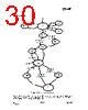
31 / 67 page  CC1150 SWRS037A Page 31 of 60 A simplified state diagram, together with typical usage and current consumption, is shown in Figure 7 on page 17. The complete radio control state diagram is shown in Figure 16. The numbers refer to the state number readable in the MARCSTATE status register. This functionality is primarily for test purposes. 16.1 Power on Start-up Sequence When the power supply is turned on, the system must be reset. This is achieved by one of the two sequences described below, i.e. Automatic power-on reset or manual reset. After the automatic power-on reset or manual reset it is also recommended to change the signal that is output on the GDO0 pin. The default setting is to output a clock signal with a frequency of CLK_XOSC/192, but to optimize performance in TX, an alternative GDO setting should be selected from the settings found in Table 24 on page 38. 16.1.1 Automatic POR A power-on reset circuit is included in the CC1150. The minimum requirements stated in Section 4.7 must be followed for the power-on reset to function properly. The internal power- up sequence is completed when CHIP_RDYn goes low. CHIP_RDYn is observed on the SO pin after CSn is pulled low. See Section 10.1 for more details on CHIP_RDYn. When the CC1150 reset is completed the chip will be in the IDLE state and the crystal oscillator running. If the chip has had sufficient time for the crystal oscillator and voltage regulator to stabilize after the power-on-reset, the SO pin will go low immediately after taking CSn low. If CSn is taken low before reset is completed the SO pin will first go high, indicating that the crystal oscillator and voltage regulator is not stabilized, before going low as shown in Figure 17. Figure 17: Power-on Reset 16.1.2 Manual Reset The other global reset possibility on CC1150 is the SRES command strobe. By issuing this strobe, all internal registers and states are set to the default, IDLE state. The power-up sequence is as follows (see Figure 18): • Set SCLK = 1 and SI = 0. • Strobe CSn low / high. Make sure to hold CSn high for at least 40 µs relative to pulling CSn low. • Pull CSn low and wait for SO to go low (CHIP_RDYn). • Issue the SRES strobe on the SI line. • When SO goes low again, reset is complete and the chip is in the IDLE state. Figure 18: Power-up with SRES Note that the above reset procedure is only required just after the power supply is first turned on. If the user wants to reset the CC1150 after this, it is only necessary to issue an SRES command strobe. It is recommended to always send a SRES command strobe on the SPI interface after power-on even though power-on reset is used. 16.2 Crystal Control The crystal oscillator is automatically turned on when CSn goes low. It will be turned off if the SXOFF or SPWD command strobes are issued; the state machine then goes to XOFF or SLEEP respectively. This can only be done from IDLE state. The XOSC will be turned off when CSn is released (goes high). The XOSC will be automatically turned on again when |
|
Enlace URL |
| ¿ALLDATASHEET es útil para Ud.? [ DONATE ] |
Todo acerca de Alldatasheet | Publicidad | Contáctenos | Política de Privacidad | Enlace a la hoja de datos | Intercambio de Enlaces | Lista de Fabricantes All Rights Reserved©Alldatasheet.com |
| Russian : Alldatasheetru.com | Korean : Alldatasheet.co.kr | Spanish : Alldatasheet.es | French : Alldatasheet.fr | Italian : Alldatasheetit.com Portuguese : Alldatasheetpt.com | Polish : Alldatasheet.pl | Vietnamese : Alldatasheet.vn Indian : Alldatasheet.in | Mexican : Alldatasheet.com.mx | British : Alldatasheet.co.uk | New Zealand : Alldatasheet.co.nz |
|
Family Site : ic2ic.com |
icmetro.com |
 Spanish ▼
 English
 Chinese
 German
 Japanese
 Russian
 Korean
 Spanish
 French
 Italian
 Portuguese
 Polish
 Vietnamese
 Indian
 Mexican
 British
 New Zealand