 |
Motor de Búsqueda de Datasheet de Componentes Electrónicos |
|
|
Motor de Búsqueda de Datasheet de Componentes Electrónicos |
|
The question interval is too short.
Please try again in a few seconds.

Hello, Please ask a question about 74HC1G66-Q100 Datasheet
# Example questions:
➢ Referring to table 12, what is the typical -3db frequency response for the 74hc1g66-q100 at a supply voltage of 9v with a 50pf load capacitor and a 10kω load resistor?
➢ What are the key differences in the test conditions used for the 74hc1g66-q100 and 74hct1g66-q100 regarding input voltage (vi) and its impact on the measurements?
➢ What is the typical total harmonic distortion (thd) at 1 khz with a 4.5v supply and 4.0v peak-to-peak input voltage for both the 74hc1g66-q100 and 74hct1g66-q100?
| Part No. | 74HC1G66-Q100 |
| Manufacturer | NEXPERIA |
| Size | 730 Kbytes |
| Pages | 19 pages |
| Description | Single-pole single-throw analog switch |



1. General Description:
️· These are single-pole, single-throw (SPST) analog switches. They can be used to connect or disconnect an analog signal.
️· 74HC1G66: Designed for lower voltage operation (typically 2V to 6V) and is CMOS-based.
️· 74HCT1G66: Designed for both 2V to 6V and 3V to 5.5V operation. It's TTL compatible.
2. Key Electrical Characteristics (Differentiated by Part):
️· Supply Voltage:
- 74HC1G66: 2V to 6V
- 74HCT1G66: 2V to 6V *or* 3V to 5.5V
️· Input Voltage Levels:
- 74HC1G66: VCC or Ground for switching
- 74HCT1G66: VCC or Ground, designed for TTL compatibility.
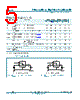
️· On Resistance (R<sub>ON</sub>): This is the resistance when the switch is closed. Lower is better.
- Both parts have a typical R<sub>ON</sub> around 17 - 25 Ohms
️· Off Isolation: This is a measure of how much the signal is blocked when the switch is open. Higher is better.
- Both have typical off isolation figures around -50dB.
️· Insertion Loss: This measures how much the signal strength is reduced when the switch is closed. Lower is better
- Both parts exhibit insertion loss around -0.5 dB
3. Timing Characteristics (Propagation Delay, Enable/Disable Times):
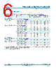
️· Propagation Delay (t<sub>PD</sub>): The time it takes for the output to respond to an input. Lower is better.
- Both parts have propagation delays around 15-18 ns.
️· Enable/Disable Times (t<sub>EN</sub>, t<sub>DIS</sub>): The time it takes for the switch to turn on/off.
- Both parts exhibit enable/disable times under 36 ns
4. Dynamic Characteristics:
️· Total Harmonic Distortion (THD): A measure of signal distortion. Lower is better.
- 74HC1G66: THD is typically around 0.04% at lower frequencies and 0.12% at higher frequencies.
- 74HCT1G66: Similar but slightly higher numbers.
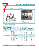
️· -3 dB Frequency Response: Indicates the usable frequency range of the switch. Higher is better.
- Both parts have a typical -3 dB frequency response around 200 MHz.
5. Power Dissipation:
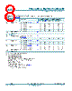
️· C<sub>PD</sub> (Power Dissipation Capacitance): This is used to calculate dynamic power dissipation. The dynamic power is significant, particularly at higher frequencies. The datasheet provides a formula for calculating dynamic power.
6. Test Conditions & Measurements:
️· The datasheet provides detailed test circuits and waveforms to demonstrate how the measurements were taken. This is important for understanding the context of the specified values.
️· Most measurements are performed at T<sub>amb</sub> = 25°C.
Key Differences Summarized (74HC1G66 vs. 74HCT1G66):
| Feature | 74HC1G66 | 74HCT1G66 |
|---|---|---|
| Supply Voltage | 2-6V | 2-6V or 3-5.5V |
| Compatibility | CMOS | TTL Compatible |
| THD | Lower | Slightly Higher |
1. General Description:
️· These are single-pole, single-throw (SPST) analog switches. They can be used to connect or disconnect an analog signal.
️· 74HC1G66: Designed for lower voltage operation (typically 2V to 6V) and is CMOS-based.
️· 74HCT1G66: Designed for both 2V to 6V and 3V to 5.5V operation. It's TTL compatible.
2. Key Electrical Characteristics (Differentiated by Part):
️· Supply Voltage:
- 74HC1G66: 2V to 6V
- 74HCT1G66: 2V to 6V *or* 3V to 5.5V
️· Input Voltage Levels:
- 74HC1G66: VCC or Ground for switching
- 74HCT1G66: VCC or Ground, designed for TTL compatibility.
️· On Resistance (R<sub>ON</sub>): This is the resistance when the switch is closed. Lower is better.
- Both parts have a typical R<sub>ON</sub> around 17 - 25 Ohms
️· Off Isolation: This is a measure of how much the signal is blocked when the switch is open. Higher is better.
- Both have typical off isolation figures around -50dB.
️· Insertion Loss: This measures how much the signal strength is reduced when the switch is closed. Lower is better
- Both parts exhibit insertion loss around -0.5 dB
3. Timing Characteristics (Propagation Delay, Enable/Disable Times):
️· Propagation Delay (t<sub>PD</sub>): The time it takes for the output to respond to an input. Lower is better.
- Both parts have propagation delays around 15-18 ns.
️· Enable/Disable Times (t<sub>EN</sub>, t<sub>DIS</sub>): The time it takes for the switch to turn on/off.
- Both parts exhibit enable/disable times under 36 ns
4. Dynamic Characteristics:
️· Total Harmonic Distortion (THD): A measure of signal distortion. Lower is better.
- 74HC1G66: THD is typically around 0.04% at lower frequencies and 0.12% at higher frequencies.
- 74HCT1G66: Similar but slightly higher numbers.
️· -3 dB Frequency Response: Indicates the usable frequency range of the switch. Higher is better.
- Both parts have a typical -3 dB frequency response around 200 MHz.
5. Power Dissipation:
️· C<sub>PD</sub> (Power Dissipation Capacitance): This is used to calculate dynamic power dissipation. The dynamic power is significant, particularly at higher frequencies. The datasheet provides a formula for calculating dynamic power.
6. Test Conditions & Measurements:
️· The datasheet provides detailed test circuits and waveforms to demonstrate how the measurements were taken. This is important for understanding the context of the specified values.
️· Most measurements are performed at T<sub>amb</sub> = 25°C.
Key Differences Summarized (74HC1G66 vs. 74HCT1G66):
| Feature | 74HC1G66 | 74HCT1G66 |
|---|---|---|
| Supply Voltage | 2-6V | 2-6V or 3-5.5V |
| Compatibility | CMOS | TTL Compatible |
| THD | Lower | Slightly Higher |
| Part No. | 74HC1G66-Q100 |
| Manufacturer | NEXPERIA |
| Size | 730 Kbytes |
| Pages | 19 pages |
| Description | Single-pole single-throw analog switch |
| ¿ALLDATASHEET es útil para Ud.? [ DONATE ] |
Todo acerca de Alldatasheet | Publicidad | Contáctenos | Política de Privacidad | Enlace a la hoja de datos | Intercambio de Enlaces | Lista de Fabricantes All Rights Reserved©Alldatasheet.com |
| Russian : Alldatasheetru.com | Korean : Alldatasheet.co.kr | Spanish : Alldatasheet.es | French : Alldatasheet.fr | Italian : Alldatasheetit.com Portuguese : Alldatasheetpt.com | Polish : Alldatasheet.pl | Vietnamese : Alldatasheet.vn Indian : Alldatasheet.in | Mexican : Alldatasheet.com.mx | British : Alldatasheet.co.uk | New Zealand : Alldatasheet.co.nz |
|
Family Site : ic2ic.com |
icmetro.com |
 Spanish ▼
  English
 Chinese
 German
 Japanese
 Russian
 Korean
 French
 Italian
 Portuguese
 Polish
 Vietnamese
 Indian
 Mexican
 British
 New Zealand