|
Motor de Búsqueda de Datasheet de Componentes Electrónicos |
|
|
Motor de Búsqueda de Datasheet de Componentes Electrónicos |
|
MC7660 Datasheet(PDF) 6 Page - ON Semiconductor |
|
|
|||||||||||||||||||||||||||||
MC7660 Datasheet(HTML) 6 Page - ON Semiconductor |
|
|
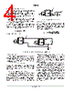
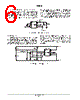
6 / 12 page  MC7660 http://onsemi.com 6 Efficient Positive Voltage Multiplication/Conversion Since the switches that allow the charge pumping operation are bidirectional, the charge transfer can be performed backwards as easily as forwards. Figure 10 shows a MC7660 transforming –5V to +5V (or +5V to +10V, etc.). The only problem here is that the internal clock and switch–drive section will not operate until some positive voltage has been generated. An initial inefficient pump, as shown in Figure 9, could be used to start this circuit up, after which it will bypass the other (D1 and D2 in Figure 9 would never turn on), or else the diode and resistor shown dotted in Figure 10 can be used to ”force” the internal regulator on. Figure 10. Positive Voltage Conversion MC7660 1 2 3 4 8 7 6 5 VOUT = –V– C1 + V– INPUT + 10 mF 1 M W 10 mF Voltage Splitting The same bidirectional characteristics used in Figure 10 can also be used to split a higher supply in half, as shown in Figure 11. The combined load will be evenly shared between the two sides. Once again, a high value resistor to the LV pin ensures start–up. Because the switches share the load in parallel, the output impedance is much lower than in the standard circuits, and higher currents can be drawn from the device. By using this circuit, and then the circuit of Figure 5, +15V can be converted (via +7.5V and –7.5V) to a nominal –15V, though with rather high series resistance (~250 W). Figure 11. Splitting a Supply in Half MC7660 1 2 3 4 8 7 6 5 1 M W 100 k W 100 k W 50 mF 50 mF + 50 mF + + – RL1 RL2 V OUT + V) * V– 2 – V– V+ |
|
|
Enlace URL |
| ¿ALLDATASHEET es útil para Ud.? [ DONATE ] |
Todo acerca de Alldatasheet | Publicidad | Contáctenos | Política de Privacidad | Enlace a la hoja de datos | Intercambio de Enlaces | Lista de Fabricantes All Rights Reserved©Alldatasheet.com |
| Russian : Alldatasheetru.com | Korean : Alldatasheet.co.kr | Spanish : Alldatasheet.es | French : Alldatasheet.fr | Italian : Alldatasheetit.com Portuguese : Alldatasheetpt.com | Polish : Alldatasheet.pl | Vietnamese : Alldatasheet.vn Indian : Alldatasheet.in | Mexican : Alldatasheet.com.mx | British : Alldatasheet.co.uk | New Zealand : Alldatasheet.co.nz |
|
Family Site : ic2ic.com |
icmetro.com |
 Spanish ▼
 English
 Chinese
 German
 Japanese
 Russian
 Korean
 Spanish
 French
 Italian
 Portuguese
 Polish
 Vietnamese
 Indian
 Mexican
 British
 New Zealand