|
Motor de Búsqueda de Datasheet de Componentes Electrónicos |
|
|
Motor de Búsqueda de Datasheet de Componentes Electrónicos |
|
AS1124 Datasheet(PDF) 12 Page - List of Unclassifed Manufacturers |
|
|
|||||||||||||||||||||||||||||
AS1124 Datasheet(HTML) 12 Page - List of Unclassifed Manufacturers |
|
|
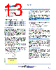
12 / 21 page  AS1124 Akros Silicon, inc. 6399 San Ignacio Avenue, Suite 250, San Jose, CA 95119 USA 408.746.9000 www.AkrosSilicon.com 12 AS1124 OVERVIEW The AS1124 is a fully integrated PD that provides the functions required for power over Ethernet (PoE) applications. The optimized architecture of the AS1124 reduces external component cost in a small footprint while delivering high performance. Figure 15 - Top-Level Block Diagram of the AS1124 RECTIFICATION & PROTECTION To protect against polarity reversal and provide automatic polarity correction, the AS1124 includes an integrated bridge for rectification, with over voltage and transient protection, before passing to the switch and DC-DC controller. By Integrating the diodes and protection circuitry, Akros has produced a solution that provides a much faster response to surge events. The design limits stray surge current from passing through sensitive circuits, such as the Ethernet PHY device and enables a low impedance safe discharge paths directly back to the earth ground. The protection circuit itself is carefully designed to ensure that during these surge events, where currents can sometime be as high as 30A, voltages do not exceed critical breakdown and spark gap limits so they themselves are not destroyed by the event. PD Controller The AS1124 PD Control interface is designed to provide full PD functionality for IEEE 802.3af compliant systems, with programmable support for the standard PD control functions. The PD Control provides the following major functions: 1. Provides a resistance for signature detection. 2. Provides classification currents for power classification. 3. Provides PD full power. 4. Manages power and thermal protection overrides, including UVLO (under voltage lockout). Modes of Operation The AS1124 has five operating modes: 1. Reset —the classification state machine is reset, and all blocks are disabled. 2. Signature Detection —The PD signature resistance is applied across the input. 3. Classification —PD indicates power requirements to the PSE. 4. Idle —This state is entered after classification, and remains here until full-power input voltage is applied. 5. ON —The PD is enabled, and supplies power to the DC-DC controller and the local application circuitry. As the supply voltage from the PSE increases from 0V, the AS1124 transitions through the modes of operation in this sequence: If no PSE is present, line voltage will be zero, which will hold the AS1124 in the reset state, and the AS1124 does not affect the Ethernet link function. Reset When the voltage supplied to the AS1124 drops below the signature voltage range (i.e. <2.7V), the chip will enter the reset state. In the reset state, the AS1124 consumes very little power. Signature Detection Mode During signature detection, the PSE applies a voltage to the AS1124 PD to read its power signature. The reading of the signature determines whether or not a PD is present and, if so, allows the PSE to determine the power class the PD belongs to. To detect a PD, the PSE applies two voltages in the signature voltage range, and extracts a signature resistance value from the I-V slope. Valid resistance (I-V slope) values are between 23.75kΩ and 26.25kΩ. For the AS1124, signature resistance is generated by an external resistor between VDD48I and GND. Typically this is a 26.7kΩ, 1% resistor. Classification Mode Each class represents a power allocation level for a PD, so that PSE can manage power between multiple PDs. IEEE® Std. 802.3af-2003 defines classes of power levels for PDs as shown in Error! Reference source not found. The AS1124 supports “two stage” classification for draft IEEE® Std. 802.3at r0.9, as shown in Figure 5. To classify the PD, the PSE presents a voltage between 14.5V and 20.5V to the PD and determines its class by measuring the load current the PD sinks. The AS1124 allows the user to program the classification current via an external resistor in the RCLASS pin. Current, power levels and programming resistor values for each class are shown in Table 7. |
|
|
Enlace URL |
| ¿ALLDATASHEET es útil para Ud.? [ DONATE ] |
Todo acerca de Alldatasheet | Publicidad | Contáctenos | Política de Privacidad | Enlace a la hoja de datos | Intercambio de Enlaces | Lista de Fabricantes All Rights Reserved©Alldatasheet.com |
| Russian : Alldatasheetru.com | Korean : Alldatasheet.co.kr | Spanish : Alldatasheet.es | French : Alldatasheet.fr | Italian : Alldatasheetit.com Portuguese : Alldatasheetpt.com | Polish : Alldatasheet.pl | Vietnamese : Alldatasheet.vn Indian : Alldatasheet.in | Mexican : Alldatasheet.com.mx | British : Alldatasheet.co.uk | New Zealand : Alldatasheet.co.nz |
|
Family Site : ic2ic.com |
icmetro.com |
 Spanish ▼
 English
 Chinese
 German
 Japanese
 Russian
 Korean
 Spanish
 French
 Italian
 Portuguese
 Polish
 Vietnamese
 Indian
 Mexican
 British
 New Zealand