|
Motor de Búsqueda de Datasheet de Componentes Electrónicos |
|
|
Motor de Búsqueda de Datasheet de Componentes Electrónicos |
|
HIP2103-4DEMO2Z Datasheet(PDF) 23 Page - Renesas Technology Corp |
|
|
|||||||||||||||||||||||||||||
HIP2103-4DEMO2Z Datasheet(HTML) 23 Page - Renesas Technology Corp |
|
|
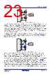
23 / 31 page  HIP2103, HIP2104 6. Application Examples FN8276 Rev.2.0 Page 23 of 30 Feb 25, 2021 The value of RHS is determined by how much average current in the clamping diode is acceptable. Current in the low-side FET flows through the body diode during the dead time resulting with a negative voltage on HS that is typically about -1.5V. When the low-side FET is turned on, the current through the body diode is shunted away into the channel and the conduction voltage from source to drain is typically much less than the conduction voltage through the body diode. Consequently, significant current flows in the clamping diode only during the dead time. Because the dead time is much less than the low-side FET’s on-time, the resulting average current in the clamping diode is very low. The value of RHS is then chosen to limit the peak current in the clamping diode and usually just a few ohms is necessary. The methods to clamp the negative transients with diodes can still result with high frequency oscillations on the HS node depending on the parasitics of the PCB design. An alternative to the clamping diode in Figure 26 is a small value capacitor instead of the diode. This capacitor and RHS is very effective for minimizing the negative spike amplitude and oscillations. However, this solution also has its limitations. Depending on the value of the filter capacitor and the PWM switching frequency, RHS can dissipate significant power because the voltage on the capacitor is switching between the bridge voltage and ground. Usually, the power dissipated by RHS is small because the switching frequency for most motor drives is <20kHz and the value used for Cfilter is typically about 1000pF. Another issue is that the charge on Cfilter is partially transferred to the gate of the high-side FET when the low-side FET turns on. When the phase node goes low, a voltage is impressed across RHS as shown in Figure 27. Because HO is low, the voltage across RHS is also across the gate of the high-side FET. If the filter capacitor is very large, the voltage on the gate approaches the bridge voltage turning on the high-side FET resulting with shoot-through. Fortunately, the voltage across RHS is much less than the bridge voltage for two reasons. First, the voltage across RHS is determined by the turn-on time of the low-side FET. As the low-side FET is turning on, the charge on the filter capacitor is depleting lessening the voltage across RHS. Also, because the relatively large gate capacitance of the high-side FET is in parallel with RHS, the voltage impressed on the gate is further reduced. In a Figure 26. Resistor and Diode Negative Transient Clamp Figure 27. Resistor and Capacitor Negative Transient Filter VSS HS LO HO Inductive Load + - + - RHS HB CBOOT VSS HS LO HO Inductive Load RHS HB CBOOT + _ Cfilter IBAT, 0kHz |
|
Enlace URL |
| ¿ALLDATASHEET es útil para Ud.? [ DONATE ] |
Todo acerca de Alldatasheet | Publicidad | Contáctenos | Política de Privacidad | Enlace a la hoja de datos | Intercambio de Enlaces | Lista de Fabricantes All Rights Reserved©Alldatasheet.com |
| Russian : Alldatasheetru.com | Korean : Alldatasheet.co.kr | Spanish : Alldatasheet.es | French : Alldatasheet.fr | Italian : Alldatasheetit.com Portuguese : Alldatasheetpt.com | Polish : Alldatasheet.pl | Vietnamese : Alldatasheet.vn Indian : Alldatasheet.in | Mexican : Alldatasheet.com.mx | British : Alldatasheet.co.uk | New Zealand : Alldatasheet.co.nz |
|
Family Site : ic2ic.com |
icmetro.com |
 Spanish ▼
 English
 Chinese
 German
 Japanese
 Russian
 Korean
 Spanish
 French
 Italian
 Portuguese
 Polish
 Vietnamese
 Indian
 Mexican
 British
 New Zealand