|
Motor de Búsqueda de Datasheet de Componentes Electrónicos |
|
|
Motor de Búsqueda de Datasheet de Componentes Electrónicos |
|
LTC3336ACBZ-2-R7 Datasheet(PDF) 15 Page - Analog Devices |
|
|
|||||||||||||||||||||||||||||
LTC3336ACBZ-2-R7 Datasheet(HTML) 15 Page - Analog Devices |
|
|
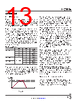
15 / 24 page  LTC3336 15 Rev. A For more information www.analog.com during this load condition. The capacitor can be sized using Equation 2 for an acceptable ripple VOUT+ – VOUT–. COUT = tLOAD • ILOAD – 0.95 • IPEAK VOUT+ – VOUT– ⎛ ⎝⎜ ⎞ ⎠⎟ (2) In Equation 2, tLOAD is the duration of the excessive tran- sient load current, IPEAK is the programmed IPEAK setting and VOUT+ – VOUT– is the desired VOUT ripple. At zero or light load conditions VOUT should not exceed the typical 5% overvoltage threshold. Otherwise, it loses some power in the 1MΩ overvoltage pull-down resistor. A standard surface mount ceramic capacitor can be used for COUT. These capacitors can be obtained from manu- facturers such as Vishay, Murata, TDK, and Taiyo Yuden. Table 3. Minimum Required Buck Output Capacitor Size for a Sleep Time of 50µs at Max Load VOUT (V) IPEAK (mA) COUT (µF) 1.2 10 6.8 1.2 30 22 1.2 100 68 1.2 300 220 2.5 10 3.3 2.5 30 10 2.5 100 33 2.5 300 100 5.0 10 2.2 5.0 30 4.7 5.0 100 22 5.0 300 47 Inductor Selection The buck is optimized to work with inductor values calcu- lated with Equation 3 or larger. The calculated values rep- resent a suitable trade-off between size and efficiency for typical applications. A larger inductor will benefit higher input voltage applications by reducing the switching fre- quency of the P-channel MOSFET switch, thereby improv- ing efficiency by reducing gate charge loss. Choose an inductor with a saturation current rating, ISAT, greater than the programmed IPEAK setting. The DC Resistance (DCR) of the inductor can have an impact on efficiency as it is a source of loss. Trade-offs between price, size, and DCR should be evaluated. Equation 3 can be used to calculate the minimum inductor value that works well with the LTC3336 depending on VIN, VOUT, IPEAK and maxi- mum switching frequency ƒ. A good target for switching frequency is 2MHz. Examples of inductor series to choose from: LPS4018 (0.56μH to 1000μH), MSS7348 (3.3μH to 1000μH), and MSS1210 (10μH to 10,000μH). L = 1 ƒ • 10% •IPEAK • 1 VIN − VOUT + 1 VOUT ⎛ ⎝⎜ ⎞ ⎠⎟ (3) Explanation of symbols used in Equation 3 and how they are derived: T = L • ∆I VL T = 1 ƒ ∆I =IPEAK −IVALLEY = 10% •IPEAK VL = Voltage Across Inductor ƒ = Switching Frequency T = TON + TOFF TON = L • ∆I VIN − VOUT duration of P-Channel MOSFET On TOFF = L • ∆I VOUT duration of P-Channel MOSFET Off Dynamic Output Voltage Change The selection bits OUT[3:0] can be driven from the out- puts of a microcontroller and dynamically changed while the buck is running. A start-up default voltage, VDEFAULT, can be set with one (or more) pins tied high. Refer to Table 4 and the APPLICATIONS INFORMATION |
|
|
Enlace URL |
| ¿ALLDATASHEET es útil para Ud.? [ DONATE ] |
Todo acerca de Alldatasheet | Publicidad | Contáctenos | Política de Privacidad | Enlace a la hoja de datos | Intercambio de Enlaces | Lista de Fabricantes All Rights Reserved©Alldatasheet.com |
| Russian : Alldatasheetru.com | Korean : Alldatasheet.co.kr | Spanish : Alldatasheet.es | French : Alldatasheet.fr | Italian : Alldatasheetit.com Portuguese : Alldatasheetpt.com | Polish : Alldatasheet.pl | Vietnamese : Alldatasheet.vn Indian : Alldatasheet.in | Mexican : Alldatasheet.com.mx | British : Alldatasheet.co.uk | New Zealand : Alldatasheet.co.nz |
|
Family Site : ic2ic.com |
icmetro.com |
 Spanish ▼
 English
 Chinese
 German
 Japanese
 Russian
 Korean
 Spanish
 French
 Italian
 Portuguese
 Polish
 Vietnamese
 Indian
 Mexican
 British
 New Zealand