|
Motor de Búsqueda de Datasheet de Componentes Electrónicos |
|
|
Motor de Búsqueda de Datasheet de Componentes Electrónicos |
|
M30620FCAFP Datasheet(PDF) 146 Page - Mitsubishi Electric Semiconductor |
|
|
|||||||||||||||||||||||||||||
M30620FCAFP Datasheet(HTML) 146 Page - Mitsubishi Electric Semiconductor |
|
|
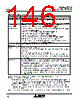
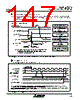
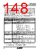
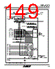
146 / 274 page  Mitsubishi microcomputers M16C / 62A Group SINGLE-CHIP 16-BIT CMOS MICROCOMPUTER S I/O3, 4 146 Table 1.16.13. Specifications of S I/O3, 4 Note 1: n is a value from 0016 through FF16 set in the S I/Oi bit rate generator (i = 3, 4). Note 2: With the external clock selected: • Before data can be written to the SI/Oi transmit/receive register (addresses 036016, 036416), the CLKi pin input must be in the high state. Also, before rewriting the SI/Oi Control Register (addresses 036216, 036616)’s bit 7 (SOUTi initial value set bit), make sure the CLKi pin input is held high. • The S I/Oi circuit keeps on with the shift operation as long as the synchronous clock is entered in it, so stop the synchronous clock at the instant when it counts to eight. The internal clock, if selected, automatically stops. Note 3: If the internal clock is used for the synchronous clock, the transfer clock signal stops at the “H” state. Item Transfer data format Transfer clock Conditions for transmission/ reception start Interrupt request generation timing Select function Precaution Specifications • Transfer data length: 8 bits • With the internal clock selected (bit 6 of 036216, 036616 = “1”): f1/2(ni+1), f8/2(ni+1), f32/2(ni+1) (Note 1) • With the external clock selected (bit 6 of 036216, 036616 = 0):Input from the CLKi terminal (Note 2) • To start transmit/reception, the following requirements must be met: - Select the synchronous clock (use bit 6 of 036216, 036616). Select a frequency dividing ratio if the internal clock has been selected (use bits 0 and 1 of 036216, 036616). - SOUTi initial value set bit (use bit 7 of 036216, 036616)= 1. - S I/Oi port select bit (bit 3 of 036216, 036616) = 1. - Select the transfer direction (use bit 5 of 036216, 036616) -Write transfer data to SI/Oi transmit/receive register (036016, 036416) • To use S I/Oi interrupts, the following requirements must be met: - Clear the SI/Oi interrupt request bit before writing transfer data to the SI/Oi transmit/receive register (bit 3 of 004916, 004816) = 0. • Rising edge of the last transfer clock. (Note 3) • LSB first or MSB first selection Whether transmission/reception begins with bit 0 (LSB) or bit 7 (MSB) can be selected. • Function for setting an SOUTi initial value selection When using an external clock for the transfer clock, the user can choose the SOUTi pin output level during a non-transfer time. For details on how to set, see Figure 1.16.33. • Unlike UART0–2, SI/Oi (i = 3, 4) is not divided for transfer register and buffer. Therefore, do not write the next transfer data to the SI/Oi transmit/receive register (addresses 036016, 036416) during a transfer. • When the internal clock is selected for the transfer clock, SOUTi holds the last data for a 1/2 transfer clock period after it finished transferring and then goes to a high- impedance state. However, if the transfer data is written to the SI/Oi transmit/ receive register (addresses 036016, 036416) during this time, SOUTi is placed in the high-impedance state immediately upon writing and the data hold time is thereby reduced. |
|
Enlace URL |
| ¿ALLDATASHEET es útil para Ud.? [ DONATE ] |
Todo acerca de Alldatasheet | Publicidad | Contáctenos | Política de Privacidad | Enlace a la hoja de datos | Intercambio de Enlaces | Lista de Fabricantes All Rights Reserved©Alldatasheet.com |
| Russian : Alldatasheetru.com | Korean : Alldatasheet.co.kr | Spanish : Alldatasheet.es | French : Alldatasheet.fr | Italian : Alldatasheetit.com Portuguese : Alldatasheetpt.com | Polish : Alldatasheet.pl | Vietnamese : Alldatasheet.vn Indian : Alldatasheet.in | Mexican : Alldatasheet.com.mx | British : Alldatasheet.co.uk | New Zealand : Alldatasheet.co.nz |
|
Family Site : ic2ic.com |
icmetro.com |
 Spanish ▼
 English
 Chinese
 German
 Japanese
 Russian
 Korean
 Spanish
 French
 Italian
 Portuguese
 Polish
 Vietnamese
 Indian
 Mexican
 British
 New Zealand