|
Motor de Búsqueda de Datasheet de Componentes Electrónicos |
|
|
Motor de Búsqueda de Datasheet de Componentes Electrónicos |
|
CC1150-RTY1 Datasheet(PDF) 28 Page - Texas Instruments |
|
|
|||||||||||||||||||||||||||||
CC1150-RTY1 Datasheet(HTML) 28 Page - Texas Instruments |
|
|
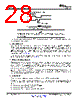
28 / 67 page  CSn SO XOSC Stable XOSC and voltage regulator switched on SI SRES 40 µs CC1150 SWRS037B – JANUARY 2006 – REVISED MARCH 2015 www.ti.com Figure 5-13. Power-up with SRES NOTE The above reset procedure is only required just after the power supply is first turned on. If the user wants to reset the CC1150 after this, it is only necessary to issue an SRES command strobe. It is recommended to always send a SRES command strobe on the SPI interface after power-on even though power-on reset is used. 5.11.2 Crystal Control The crystal oscillator is automatically turned on when CSn goes low. It will be turned off if the SXOFF or SPWD command strobes are issued; the state machine then goes to XOFF or SLEEP respectively. This can only be done from IDLE state. The XOSC will be turned off when CSn is released (goes high). The XOSC will be automatically turned on again when CSn goes low. The state machine will then go to the IDLE state. The SO pin on the SPI interface must be pulled low before the SPI interface is ready to be used; as described in Section 5.5.1. Crystal oscillator start-up time depends on crystal ESR and load capacitances. The electrical specification for the crystal oscillator can be found in Section 4.7. 5.11.3 Voltage Regulator Control The voltage regulator to the digital core is controlled by the radio controller. When the chip enters the SLEEP state, which is the state with the lowest current consumption, the voltage regulator is disabled. This occurs after CSn is released when a SPWD command strobe has been sent on the SPI interface. The chip is then in the SLEEP state. Setting CSn low again will turn on the regulator and crystal oscillator and make the chip enter the IDLE state. On the CC1150, all register values (with the exception of the MCSM0.PO_TIMEOUT field) are lost in the SLEEP state. After the chip gets back to the IDLE state, the registers will have default (reset) contents and must be reprogrammed over the SPI interface. 5.11.4 Active Mode The active transmit mode is activated by the MCU by using the STX command strobe. The frequency synthesizer must be calibrated regularly. CC1150 has one manual calibration option (using the SCAL strobe), and three automatic calibration options, controlled by the MCSM0.FS_AUTOCAL setting: • Calibrate when going from IDLE to TX (or FSTXON) • Calibrate when going from TX to IDLE • Calibrate every fourth time when going from TX to IDLE 28 Detailed Description Copyright © 2006–2015, Texas Instruments Incorporated Submit Documentation Feedback Product Folder Links: CC1150 |
|
Enlace URL |
| ¿ALLDATASHEET es útil para Ud.? [ DONATE ] |
Todo acerca de Alldatasheet | Publicidad | Contáctenos | Política de Privacidad | Enlace a la hoja de datos | Intercambio de Enlaces | Lista de Fabricantes All Rights Reserved©Alldatasheet.com |
| Russian : Alldatasheetru.com | Korean : Alldatasheet.co.kr | Spanish : Alldatasheet.es | French : Alldatasheet.fr | Italian : Alldatasheetit.com Portuguese : Alldatasheetpt.com | Polish : Alldatasheet.pl | Vietnamese : Alldatasheet.vn Indian : Alldatasheet.in | Mexican : Alldatasheet.com.mx | British : Alldatasheet.co.uk | New Zealand : Alldatasheet.co.nz |
|
Family Site : ic2ic.com |
icmetro.com |
 Spanish ▼
 English
 Chinese
 German
 Japanese
 Russian
 Korean
 Spanish
 French
 Italian
 Portuguese
 Polish
 Vietnamese
 Indian
 Mexican
 British
 New Zealand