|
Motor de Búsqueda de Datasheet de Componentes Electrónicos |
|
|
Motor de Búsqueda de Datasheet de Componentes Electrónicos |
|
AD8253ARMZ-R7 Datasheet(PDF) 17 Page - Analog Devices |
|
|
|||||||||||||||||||||||||||||
AD8253ARMZ-R7 Datasheet(HTML) 17 Page - Analog Devices |
|
|
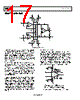
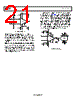
17 / 25 page  AD8253 Data Sheet Rev. B | Page 16 of 24 THEORY OF OPERATION 10kΩ 10kΩ 10kΩ 10kΩ REF OUT A3 –IN +IN WR 1.2kΩ 1.2kΩ +VS +VS –VS –VS +VS –VS +VS –VS A1 A0 2.2kΩ DGND A1 A2 DIGITAL GAIN CONTROL 2.2kΩ +VS –VS +VS –VS +VS –VS +VS –VS Figure 51. Simplified Schematic The AD8253 is a monolithic instrumentation amplifier based on the classic 3-op-amp topology, as shown in Figure 51. It is fabricated on the Analog Devices, Inc., proprietary iCMOS® process that provides precision linear performance and a robust digital interface. A parallel interface allows users to digitally program gains of 1, 10, 100, and 1000. Gain control is achieved by switching resistors in an internal precision resistor array (as shown in Figure 51). All internal amplifiers employ distortion cancellation circuitry and achieve high linearity and ultralow THD. Laser-trimmed resistors allow for a maximum gain error of less than 0.03% for G = 1 and a minimum CMRR of 100 dB for G = 1000. A pinout optimized for high CMRR over frequency enables the AD8253 to offer a guaranteed minimum CMRR over frequency of 80 dB at 20 kHz (G = 1). The balanced input reduces the parasitics that in the past had adversely affected CMRR performance. GAIN SELECTION This section describes how to configure the AD8253 for basic operation. Logic low and logic high voltage limits are listed in the Specifications section. Typically, logic low is 0 V and logic high is 5 V; both voltages are measured with respect to DGND. Refer to the specifications table (Table 2) for the permissible voltage range of DGND. The gain of the AD8253 can be set using two methods: transparent gain mode and latched gain mode. Regardless of the mode, pull-up or pull-down resistors should be used to provide a well-defined voltage at the A0 and A1 pins. Transparent Gain Mode The easiest way to set the gain is to program it directly via a logic high or logic low voltage applied to A0 and A1. Figure 52 shows an example of this gain setting method, referred to through- out the data sheet as transparent gain mode. Tie WR to the negative supply to engage transparent gain mode. In this mode, any change in voltage applied to A0 and A1 from logic low to logic high, or vice versa, immediately results in a gain change. Table 5 is the truth table for transparent gain mode, and Figure 52 shows the AD8253 configured in transparent gain mode. +15V –15V –15V A0 A1 WR +IN +5V +5V –IN 10μF0.1µF 10μF0.1µF G = 1000 DGND DGND REF AD8253 NOTE: 1. IN TRANSPARENT GAIN MODE, WR IS TIED TO −VS. THE VOLTAGE LEVELS ON A0 AND A1 DETERMINE THE GAIN. IN THIS EXAMPLE, BOTH A0 AND A1 ARE SET TO LOGIC HIGH, RESULTING IN A GAIN OF 1000. Figure 52. Transparent Gain Mode, A0 and A1 = High, G = 1000 |
|
|
Enlace URL |
| ¿ALLDATASHEET es útil para Ud.? [ DONATE ] |
Todo acerca de Alldatasheet | Publicidad | Contáctenos | Política de Privacidad | Enlace a la hoja de datos | Intercambio de Enlaces | Lista de Fabricantes All Rights Reserved©Alldatasheet.com |
| Russian : Alldatasheetru.com | Korean : Alldatasheet.co.kr | Spanish : Alldatasheet.es | French : Alldatasheet.fr | Italian : Alldatasheetit.com Portuguese : Alldatasheetpt.com | Polish : Alldatasheet.pl | Vietnamese : Alldatasheet.vn Indian : Alldatasheet.in | Mexican : Alldatasheet.com.mx | British : Alldatasheet.co.uk | New Zealand : Alldatasheet.co.nz |
|
Family Site : ic2ic.com |
icmetro.com |
 Spanish ▼
 English
 Chinese
 German
 Japanese
 Russian
 Korean
 Spanish
 French
 Italian
 Portuguese
 Polish
 Vietnamese
 Indian
 Mexican
 British
 New Zealand