|
Motor de Búsqueda de Datasheet de Componentes Electrónicos |
|
|
Motor de Búsqueda de Datasheet de Componentes Electrónicos |
|
TC1040 Datasheet(PDF) 4 Page - Microchip Technology |
|
|
|||||||||||||||||||||||||||||
TC1040 Datasheet(HTML) 4 Page - Microchip Technology |
|
|
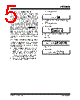
4 / 14 page  TC1040 DS21345B-page 4 © 2002 Microchip Technology Inc. 3.0 DETAILED DESCRIPTION The TC1040 is one of a series of very low power, linear building block products targeted at low voltage, single supply applications. The TC1040 minimum operating voltage is 1.8V and typical supply current is only 10 µA (fully enabled). It combines two comparators and a voltage reference in a single package. A shutdown mode is incorporated for easy adaptation to system power management schemes. During shutdown, one comparator is disabled (i.e., powered down with output at a high impedance). The “still awake” comparator and voltage reference can be used as a wake-up timer, power supply monitor, LDO controller or other continuous duty circuit function. 3.1 Comparators The TC1040 contains two comparators. The compara- tor’s input range extends beyond both supply voltages by 200mV and the outputs will swing to within several millivolts of the supplies, depending on the load current being driven. The inverting input of Comparator A and the non-inverting input of Comparator B are internally connected to the output of the voltage reference. The comparators exhibit a propagation delay and supply current which are largely independent of supply voltage. The low input bias current and offset voltage make them suitable for high impedance precision applications. Comparator B is disabled during shutdown and has a high impedance output. Comparator COMPA remains active. 3.2 Voltage Reference A 2.0 percent tolerance, internally biased, 1.20V bandgap voltage reference is included in the TC1040. It has a push-pull output capable of sourcing and sinking 50 µA. The voltage reference remains fully enabled during shutdown. 3.3 Shutdown Input SHDN at VIL disables one comparator. The SHDN input cannot be allowed to float; when not used, connect it to VDD. The disabled comparator’s output is in a high impedance state when shutdown is active. The disabled comparator’s inputs and outputs can be driven from rail-to-rail by an external voltage when the TC1040 is in shutdown. No latchup will occur when the device is driven to its enabled state when SHDN is set to VIH. 4.0 TYPICAL APPLICATIONS The TC1040 lends itself to a wide variety of applications, particularly in battery powered systems. It typically finds application in power management, processor supervisory and interface circuitry. 4.1 Wake-Up Timer Many microcontrollers have a low-power “sleep” mode that significantly reduces their supply current. Typically, the microcontroller is placed in this mode via a software instruction, and returns to a fully-enabled state upon reception of an external signal (“wake-up”). The wake- up signal is usually supplied by a hardware timer. Most system applications demand that this timer have a long duration (typically seconds or minutes), and consume as little supply current as possible. The circuit shown in Figure 4-1 is a wake-up timer made from Comparator A. (Comparator A is used because the wake-up timer must operate when SHDN is active.) Capacitor C1 charges through R1 until a voltage equal to VR is reached, at which point the “wake-up” is driven active. Upon wake-up, the microcontroller resets the timer by forcing a logic low on a dedicated, open drain I/O port pin. This discharges C1 through R4 (the value of R4 is chosen to limit maximum current sunk by the I/O port pin). With a 3V supply, the circuit as shown consumes typically 8 µA and furnishes a nominal timer duration of 25 seconds. FIGURE 4-1: WAKE-UP TIMER Wake-Up R1 5M R4 VR C1 10 µF VDD VDD – + I/O* *Open Drain Port Pin Microcontroller COMPA 1/2 TC1040 |
|
|
Enlace URL |
| ¿ALLDATASHEET es útil para Ud.? [ DONATE ] |
Todo acerca de Alldatasheet | Publicidad | Contáctenos | Política de Privacidad | Enlace a la hoja de datos | Intercambio de Enlaces | Lista de Fabricantes All Rights Reserved©Alldatasheet.com |
| Russian : Alldatasheetru.com | Korean : Alldatasheet.co.kr | Spanish : Alldatasheet.es | French : Alldatasheet.fr | Italian : Alldatasheetit.com Portuguese : Alldatasheetpt.com | Polish : Alldatasheet.pl | Vietnamese : Alldatasheet.vn Indian : Alldatasheet.in | Mexican : Alldatasheet.com.mx | British : Alldatasheet.co.uk | New Zealand : Alldatasheet.co.nz |
|
Family Site : ic2ic.com |
icmetro.com |
 Spanish ▼
 English
 Chinese
 German
 Japanese
 Russian
 Korean
 Spanish
 French
 Italian
 Portuguese
 Polish
 Vietnamese
 Indian
 Mexican
 British
 New Zealand