|
Motor de Búsqueda de Datasheet de Componentes Electrónicos |
|
|
Motor de Búsqueda de Datasheet de Componentes Electrónicos |
|
MA4AGSW3 Datasheet(PDF) 5 Page - M/A-COM Technology Solutions, Inc. |
|
|
|||||||||||||||||||||||||||||
MA4AGSW3 Datasheet(HTML) 5 Page - M/A-COM Technology Solutions, Inc. |
|
|
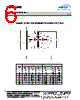
5 / 7 page  5 SP3T AlGaAs PIN Diode Switch Rev. V7 MA4AGSW3 • North America Tel: 800.366.2266 • Europe Tel: +353.21.244.6400 • India Tel: +91.80.43537383 • China Tel: +86.21.2407.1588 Visit www.macomtech.com for additional data sheets and product information. M/A-COM Technology Solutions Inc. and its affiliates reserve the right to make changes to the product(s) or information contained herein without notice. ADVANCED: Data Sheets contain information regarding a product M/A-COM Technology Solutions is considering for development. Performance is based on target specifications, simulated results, and/or prototype measurements. Commitment to develop is not guaranteed. PRELIMINARY: Data Sheets contain information regarding a product M/A-COM Technology Solutions has under development. Performance is based on engineering tests. Specifications are typical. Mechanical outline has been fixed. Engineering samples and/or test data may be available. Commitment to produce in volume is not guaranteed. Operation of the MA4AGSW3 Switch The simultaneous application of a negative DC current to the low loss port and positive DC current to the remaining isolated switching ports is required for the operation of the MA4AGSW3, AlGaAs, PIN switch. The backside area of the die is the RF and DC return ground plane. The DC return is connected to the common port J1. The forward bias voltage at J2, J3 & J4 will not exceed ±1.6 volts and is typically ± 1.4 volts with supply current of ± 30mA). In the low loss state, the series diode must be forward biased and the shunt diode reverse biased. While for the Isolated port, the shunt diode is forward biased and the series diode is reverse biased. The bias network design shown below should yield > 30 dB RF to DC Isolation. Available for use in conjunction with M/A-COM Tech’s line of AlGaAs switches are two, fully integrated, broad- band, monolithic, bias networks which may be used as an alternative to the suggested individual component bias network shown below. Refer to datasheets for the MA4BN1840-1 and MA4BN1840-2 for additional information. The lowest insertion loss, P1dB, IP 3, and switching speed is achieved by using a voltage pull-up resistor in the DC return path, (J1). A minimum value of | -2V | is recommended at this return node, which is achievable with a standard, ± 5V TTL Controlled PIN Diode Driver. MA4AGSW3 Schematic with a Typical External 2-18 GHz Bias Network TYPICAL DRIVER CONNECTIONS CONTROL LEVEL (DC CURRENT) CONDITION OF RF OUTPUT J2 J3 J4 J2-J1 J3-J1 J4-J1 -10mA +10mA +10mA Low Loss Isolation Isolation +10mA -10mA +10mA Isolation Low Loss Isolation +10mA +10mA -10mA Isolation Isolation Low Loss |
|
|
Enlace URL |
| ¿ALLDATASHEET es útil para Ud.? [ DONATE ] |
Todo acerca de Alldatasheet | Publicidad | Contáctenos | Política de Privacidad | Enlace a la hoja de datos | Intercambio de Enlaces | Lista de Fabricantes All Rights Reserved©Alldatasheet.com |
| Russian : Alldatasheetru.com | Korean : Alldatasheet.co.kr | Spanish : Alldatasheet.es | French : Alldatasheet.fr | Italian : Alldatasheetit.com Portuguese : Alldatasheetpt.com | Polish : Alldatasheet.pl | Vietnamese : Alldatasheet.vn Indian : Alldatasheet.in | Mexican : Alldatasheet.com.mx | British : Alldatasheet.co.uk | New Zealand : Alldatasheet.co.nz |
|
Family Site : ic2ic.com |
icmetro.com |
 Spanish ▼
 English
 Chinese
 German
 Japanese
 Russian
 Korean
 Spanish
 French
 Italian
 Portuguese
 Polish
 Vietnamese
 Indian
 Mexican
 British
 New Zealand