|
Motor de Búsqueda de Datasheet de Componentes Electrónicos |
|
|
Motor de Búsqueda de Datasheet de Componentes Electrónicos |
|
M38045FFHKP Datasheet(PDF) 80 Page - Renesas Technology Corp |
|
|
|||||||||||||||||||||||||||||
M38045FFHKP Datasheet(HTML) 80 Page - Renesas Technology Corp |
|
|
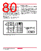
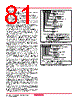
80 / 116 page  Rev.1.01 Jan 25, 2005 page 80 of 114 REJ03B0131-0101Z 3804 Group (Spec. H) Fig. 77 Block diagram of built-in flash memory q Boot Mode The control program for CPU rewrite mode must be written into the User ROM or Boot ROM area in parallel I/O mode beforehand. (If the control program is written into the Boot ROM area, the stan- dard serial I/O mode becomes unusable.) See Figure 77 for details about the Boot ROM area. Normal microcomputer mode is entered when the microcomputer is reset with pulling CNVSS pin low. In this case, the CPU starts operating using the control program in the User ROM area. When the microcomputer is reset and the CNVSS pin high after pulling the P45/TxD1 pin and CNVss pin high, the CPU starts op- erating (start address of program is stored into addresses FFFC16 and FFFD16) using the control program in the Boot ROM area. This mode is called the “Boot mode”. Also, User ROM area can be rewritten using the control program in the Boot ROM area. q Block Address Block addresses refer to the maximum address of each block. These addresses are used in the block erase command. q CPU Rewrite Mode In CPU rewrite mode, the internal flash memory can be operated on (read, program, or erase) under control of the Central Process- ing Unit (CPU). In CPU rewrite mode, only the User ROM area shown in Figure 77 can be rewritten; the Boot ROM area cannot be rewritten. Make sure the program and block erase commands are issued for only the User ROM area and each block area. The control program for CPU rewrite mode can be stored in either User ROM or Boot ROM area. In the CPU rewrite mode, because the flash memory cannot be read from the CPU, the rewrite con- trol program must be transferred to internal RAM area before it can be executed. SFR area Internal RAM area (2K bytes) 000016 004016 083F16 SFR area Internal flash memory area (60K bytes) 0FE016 RAM FFFF16 0FFF16 100016 User ROM area Data block B: 2K bytes 100016 180016 E00016 C00016 FFFF16 F00016 FFFF16 Boot ROM area 4K bytes Notes 1: The boot ROM area can be rewritten in a paral- lel I/O mode. (Access to except boot ROM area is disablrd.) 2: To specify a block, use the maximum address in the block. Block 3: 24K bytes 200016 800016 Data block A: 2K bytes Block 2: 16K bytes Block 1: 8 K bytes Block 0: 8 K bytes |
|
Enlace URL |
| ¿ALLDATASHEET es útil para Ud.? [ DONATE ] |
Todo acerca de Alldatasheet | Publicidad | Contáctenos | Política de Privacidad | Enlace a la hoja de datos | Intercambio de Enlaces | Lista de Fabricantes All Rights Reserved©Alldatasheet.com |
| Russian : Alldatasheetru.com | Korean : Alldatasheet.co.kr | Spanish : Alldatasheet.es | French : Alldatasheet.fr | Italian : Alldatasheetit.com Portuguese : Alldatasheetpt.com | Polish : Alldatasheet.pl | Vietnamese : Alldatasheet.vn Indian : Alldatasheet.in | Mexican : Alldatasheet.com.mx | British : Alldatasheet.co.uk | New Zealand : Alldatasheet.co.nz |
|
Family Site : ic2ic.com |
icmetro.com |
 Spanish ▼
 English
 Chinese
 German
 Japanese
 Russian
 Korean
 Spanish
 French
 Italian
 Portuguese
 Polish
 Vietnamese
 Indian
 Mexican
 British
 New Zealand