|
Motor de Búsqueda de Datasheet de Componentes Electrónicos |
|
|
Motor de Búsqueda de Datasheet de Componentes Electrónicos |
|
TDA7498L Datasheet(PDF) 15 Page - STMicroelectronics |
|
|
|||||||||||||||||||||||||||||
TDA7498L Datasheet(HTML) 15 Page - STMicroelectronics |
|
|
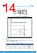
15 / 23 page  5.4 Input resistance and capacitance The input impedance is set by an internal resistor Ri = 60 kΩ (typical). An input capacitor (Ci) is required to couple the AC input signal. The equivalent circuit and frequency response of the input components are shown in Figure 23. Input circuit and frequency response. For Ci = 470 nF the high-pass filter cutoff frequency is below 20 Hz: fC = 1 / (2 * π * Ri * Ci) Figure 23. Input circuit and frequency response 5.5 Internal and external clocks The clock of the class-D amplifier can be generated internally or can be driven by an external source. If two or more class-D amplifiers are used in the same system, it is recommended that all devices operate at the same clock frequency. This can be implemented by using one TDA7498L as master clock, while the other devices are in slave mode, that is, externally clocked. The clock interconnect is via pin SYNCLK of each device. As explained below, SYNCLK is an output in master mode and an input in slave mode. 5.5.1 Master mode (internal clock) Using the internal oscillator, the output switching frequency, fSW, is controlled by the resistor, ROSC, connected to pin ROSC: fSW = 106 / [(ROSC * 16 + 182) * 4] kHz where ROSC is in kΩ. In master mode, pin SYNCLK is used as a clock output pin whose frequency is: fSYNCLK = 2 * fSW TDA7498L Input resistance and capacitance DS6539 - Rev 6 page 15/23 |
|
|
Enlace URL |
| ¿ALLDATASHEET es útil para Ud.? [ DONATE ] |
Todo acerca de Alldatasheet | Publicidad | Contáctenos | Política de Privacidad | Enlace a la hoja de datos | Intercambio de Enlaces | Lista de Fabricantes All Rights Reserved©Alldatasheet.com |
| Russian : Alldatasheetru.com | Korean : Alldatasheet.co.kr | Spanish : Alldatasheet.es | French : Alldatasheet.fr | Italian : Alldatasheetit.com Portuguese : Alldatasheetpt.com | Polish : Alldatasheet.pl | Vietnamese : Alldatasheet.vn Indian : Alldatasheet.in | Mexican : Alldatasheet.com.mx | British : Alldatasheet.co.uk | New Zealand : Alldatasheet.co.nz |
|
Family Site : ic2ic.com |
icmetro.com |
 Spanish ▼
 English
 Chinese
 German
 Japanese
 Russian
 Korean
 Spanish
 French
 Italian
 Portuguese
 Polish
 Vietnamese
 Indian
 Mexican
 British
 New Zealand