|
Motor de Búsqueda de Datasheet de Componentes Electrónicos |
|
|
Motor de Búsqueda de Datasheet de Componentes Electrónicos |
|
SC2453 Datasheet(PDF) 14 Page - Semtech Corporation |
|
|
|||||||||||||||||||||||||||||
SC2453 Datasheet(HTML) 14 Page - Semtech Corporation |
|
|
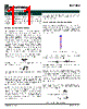
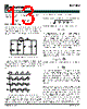
14 / 22 page  14 2005 Semtech Corp. www.semtech.com SC2453 POWER MANAGEMENT waveform. Assuming that the output current ripple is small, the following formula can be used to estimate the RMS value of the ripple current in the input capacitor. Let the duty ratio and output current of Channel 1 and Channel 2 be D 1, D2 and Io1, Io2, respectively. If D 1<0.5 and D2<0.5, then: 2 2 o 2 2 1 o 1 Cin I D I D I + ≈ If D 1>0.5 and (D1-0.5) < D2<0.5, then: 2 2 o 1 2 2 2 o 1 o 1 2 1 o Cin I) 5 . 0 D D ( ) I I )( 5 . 0 D ( I 5 . 0 I + − + + − + ≈ If D 1>0.5 and D2 < (D1-0.5) < 0.5, then: 2 2 o 2 1 2 2 o 1 o 2 2 1 o Cin I) 5 . 0 D D ( ) I I ( D I 5 . 0 I − − + + + ≈ If D 1>0.5 and D2 > 0.5, then: 2 2 o 1 2 1 o 2 2 2 o 1 o 2 1 Cin I) D 1 ( I) D 1 ( ) I I )( 1 D D ( I − + − + + − + ≈ Choosing Power MOSFET’s Choosing Power MOSFET’s Choosing Power MOSFET’s Choosing Power MOSFET’s Choosing Power MOSFET’s Main considerations in selecting the MOSFET’s are power dissipation, cost and packaging. Switching losses and conduction losses of the MOSFET’s are directly related to the total gate charge (C g) and channel on-resistance (R ds(on)). In order to judge the performance of MOSFET’s, the product of the total gate charge and on-resistance is used as a figure of merit (FOM). Transistors with the same FOM follow the same curve in Figure 5. The closer the curve is to the origin, the lower is the FOM. This means lower switching loss or lower conduction loss or both. It may be difficult to find MOSFET’s with both low C g and low Rds(on. Usually a trade-off between Rds(on and C g has to be made. 0 5 10 15 20 0 20 40 FOM:100*10^{-12} FOM:200*10^{-12} FOM:500*10^{-12} On-resistance (mOhm) 50 1 Cg 100 Rds , () Cg 200 Rds , () Cg 500 Rds , () 20 1 Rds Figure 5. Figure of Merit curves. MOSFET selection also depends on applications. In many applications, either switching loss or conduction loss dominates for a particular MOSFET. For synchronous buck converters with high input to output voltage ratios, the top MOSFET is hard switched but conducts with very low duty cycle. The bottom switch conducts at high duty cycle but switches at near zero voltage. For such applications, MOSFET’s with low C g are used for the top switch and MOSFET’s with low R ds(on) are used for the bottom switch. MOSFET power dissipation consists of a) conduction loss due to the channel resistance R ds(on), b) switching loss due to the switch rise time t r and fall time t f, and c) the gate loss due to the gate resistance R G. Top Switch: The RMS value of the top switch current is calculated as: ) 1 ( D I I 12 o rms , 1 Q 2 δ + = The conduction losses are then: P tc = IQ1,rms 2 R ds(on) R ds(on) varies with temperature and gate-source voltage. Curves showing R ds(on) variations can be found in manufacturers’ data sheet. From the Si4860 datasheet, R ds(on) is less than 8mW when Vgs is greater than 10V. However R ds(on) increases by 50% as the junction temperature increases from 25oC to 110oC. The switching losses can be estimated using the simple formula |
|
|
Enlace URL |
| ¿ALLDATASHEET es útil para Ud.? [ DONATE ] |
Todo acerca de Alldatasheet | Publicidad | Contáctenos | Política de Privacidad | Enlace a la hoja de datos | Intercambio de Enlaces | Lista de Fabricantes All Rights Reserved©Alldatasheet.com |
| Russian : Alldatasheetru.com | Korean : Alldatasheet.co.kr | Spanish : Alldatasheet.es | French : Alldatasheet.fr | Italian : Alldatasheetit.com Portuguese : Alldatasheetpt.com | Polish : Alldatasheet.pl | Vietnamese : Alldatasheet.vn Indian : Alldatasheet.in | Mexican : Alldatasheet.com.mx | British : Alldatasheet.co.uk | New Zealand : Alldatasheet.co.nz |
|
Family Site : ic2ic.com |
icmetro.com |
 Spanish ▼
 English
 Chinese
 German
 Japanese
 Russian
 Korean
 Spanish
 French
 Italian
 Portuguese
 Polish
 Vietnamese
 Indian
 Mexican
 British
 New Zealand