 |
Motor de Búsqueda de Datasheet de Componentes Electrónicos |
|
|
Motor de Búsqueda de Datasheet de Componentes Electrónicos |
|
The question interval is too short.
Please try again in a few seconds.

Hello, Please ask a question about AM27C4096-100DEB Datasheet
# Example questions:
➢ What is the typical vcc ttl standby current (icc2)?
➢ What is the minimum input high voltage (vih) specified in the dc characteristics table?
➢ What are the absolute maximum ratings for operating temperature for 'industrial (i) devices'?
| Part No. | AM27C4096-100DEB |
| Manufacturer | AMD |
| Size | 165 Kbytes |
| Pages | 12 pages |
| Description | 4 Megabit (256 K x 16-Bit) CMOS EPROM |

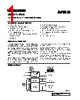
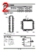
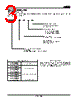
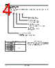
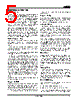
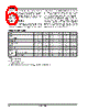
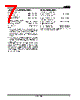
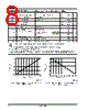
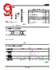
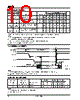


1. Chip Overview:
️· Type: Likely an EPROM (Erasable Programmable Read-Only Memory) or a related non-volatile memory chip. The "C" and "I" designations suggest commercial and industrial temperature ranges.
️· Part Number: Am27C4096
️· Capacity: Not directly stated, but the "27C4096" designation typically implies a 4096Kbit (4Mb) capacity. (Note: The full datasheet would confirm this.)
2. Operating Conditions & Ranges
️· Commercial Temperature Range (C Devices): 0°C to +70°C
️· Industrial Temperature Range (I Devices): -40°C to +85°C
️· Extended Temperature Range (E Devices): -55°C to +125°C
️· Supply Voltages (VCC):
- For ±5% devices: +4.75V to +5.25V
- For ±10% devices: +4.50V to +5.50V
️· Programming Supply Voltage (VPP): Not explicitly stated here, but critical for programming (and likely related to VCC).
3. Electrical Characteristics (Key Parameters):
️· Input Voltages (VIH, VIL): Specifies the voltage levels required for logic HIGH and LOW inputs.
️· Output Voltages (VOH, VOL): Specifies the voltage levels for output HIGH and LOW states.
️· Input/Output Leakage Currents (ILI, ILO): Quantifies the small currents that leak through the inputs and outputs when the device is not actively switching.
️· Supply Currents (ICC1, ICC2, ICC3): Indicates the current drawn by the chip under different operating conditions (active, standby). Crucial for power budget calculations.
- ICC1 (Active): ~50-60mA depending on temp range
- ICC2 (TTL Standby): ~1mA
- ICC3 (CMOS Standby): ~100µA
️· Programming Supply Current (IPP1): ~100µA
4. AC Characteristics (Timing):
️· These define the chip's speed and how quickly it responds to commands. Key parameters include:
- tAVQV (tACC): Address to Output Delay (90-250 ns) - How long it takes for the output to stabilize after an address is presented.
- tELQV (tCE): Chip Enable to Output Delay (90-250 ns)
- tGLQV (tOE): Output Enable to Output Delay (50-75 ns)
- tEHQZ / tGHQZ: High-Z Output Enable Time (30-60 ns) - Time it takes for the output to go into a high-impedance state.
- tAXQV (tOH): Output Hold Time (0 ns) – Time the output must remain stable after a change.
5. Absolute Maximum Ratings:
️· These are the limits beyond which permanent damage to the chip could occur. These are NOT operating conditions. Important to observe!
- Input Voltage: -0.5V to VCC + 0.5V. Can have short overshoots of -2V and +2V during transitions.
- Output Voltage: Same as input, potentially with overshoots.
6. Key Notes and Cautions:
️· VCC/VPP Sequencing: VCC *must* be applied before or simultaneously with VPP and removed in the reverse order. This is critical for preventing damage.
️· Socket Handling: Do *not* insert/remove the chip from a socket with VPP or VCC applied.
️· Input/Output Overshoots: While the datasheet specifies maximums, transient overshoots during transitions are allowed, but limited to short durations.
IMPORTANT CAVEATS:
️· Incomplete Data: This is just a partial excerpt from a full datasheet. Missing information includes:
- Pinout/Signal Descriptions
- Organization (Number of bits, words, or pages)
- Programming Algorithms/Conditions
- Detailed Operating Characteristics
- Packaging information
️· Version/Revision: Datasheets can change over time. The specific revision of this sheet is not stated. Always refer to the most up-to-date datasheet from the manufacturer (likely AMD or a successor company).
1. Chip Overview:
️· Type: Likely an EPROM (Erasable Programmable Read-Only Memory) or a related non-volatile memory chip. The "C" and "I" designations suggest commercial and industrial temperature ranges.
️· Part Number: Am27C4096
️· Capacity: Not directly stated, but the "27C4096" designation typically implies a 4096Kbit (4Mb) capacity. (Note: The full datasheet would confirm this.)
2. Operating Conditions & Ranges
️· Commercial Temperature Range (C Devices): 0°C to +70°C
️· Industrial Temperature Range (I Devices): -40°C to +85°C
️· Extended Temperature Range (E Devices): -55°C to +125°C
️· Supply Voltages (VCC):
- For ±5% devices: +4.75V to +5.25V
- For ±10% devices: +4.50V to +5.50V
️· Programming Supply Voltage (VPP): Not explicitly stated here, but critical for programming (and likely related to VCC).
3. Electrical Characteristics (Key Parameters):
️· Input Voltages (VIH, VIL): Specifies the voltage levels required for logic HIGH and LOW inputs.
️· Output Voltages (VOH, VOL): Specifies the voltage levels for output HIGH and LOW states.
️· Input/Output Leakage Currents (ILI, ILO): Quantifies the small currents that leak through the inputs and outputs when the device is not actively switching.
️· Supply Currents (ICC1, ICC2, ICC3): Indicates the current drawn by the chip under different operating conditions (active, standby). Crucial for power budget calculations.
- ICC1 (Active): ~50-60mA depending on temp range
- ICC2 (TTL Standby): ~1mA
- ICC3 (CMOS Standby): ~100µA
️· Programming Supply Current (IPP1): ~100µA
4. AC Characteristics (Timing):
️· These define the chip's speed and how quickly it responds to commands. Key parameters include:
- tAVQV (tACC): Address to Output Delay (90-250 ns) - How long it takes for the output to stabilize after an address is presented.
- tELQV (tCE): Chip Enable to Output Delay (90-250 ns)
- tGLQV (tOE): Output Enable to Output Delay (50-75 ns)
- tEHQZ / tGHQZ: High-Z Output Enable Time (30-60 ns) - Time it takes for the output to go into a high-impedance state.
- tAXQV (tOH): Output Hold Time (0 ns) – Time the output must remain stable after a change.
5. Absolute Maximum Ratings:
️· These are the limits beyond which permanent damage to the chip could occur. These are NOT operating conditions. Important to observe!
- Input Voltage: -0.5V to VCC + 0.5V. Can have short overshoots of -2V and +2V during transitions.
- Output Voltage: Same as input, potentially with overshoots.
6. Key Notes and Cautions:
️· VCC/VPP Sequencing: VCC *must* be applied before or simultaneously with VPP and removed in the reverse order. This is critical for preventing damage.
️· Socket Handling: Do *not* insert/remove the chip from a socket with VPP or VCC applied.
️· Input/Output Overshoots: While the datasheet specifies maximums, transient overshoots during transitions are allowed, but limited to short durations.
IMPORTANT CAVEATS:
️· Incomplete Data: This is just a partial excerpt from a full datasheet. Missing information includes:
- Pinout/Signal Descriptions
- Organization (Number of bits, words, or pages)
- Programming Algorithms/Conditions
- Detailed Operating Characteristics
- Packaging information
️· Version/Revision: Datasheets can change over time. The specific revision of this sheet is not stated. Always refer to the most up-to-date datasheet from the manufacturer (likely AMD or a successor company).
| Part No. | AM27C4096-100DEB |
| Manufacturer | AMD |
| Size | 165 Kbytes |
| Pages | 12 pages |
| Description | 4 Megabit (256 K x 16-Bit) CMOS EPROM |
| ¿ALLDATASHEET es útil para Ud.? [ DONATE ] |
Todo acerca de Alldatasheet | Publicidad | Contáctenos | Política de Privacidad | Enlace a la hoja de datos | Intercambio de Enlaces | Lista de Fabricantes All Rights Reserved©Alldatasheet.com |
| Russian : Alldatasheetru.com | Korean : Alldatasheet.co.kr | Spanish : Alldatasheet.es | French : Alldatasheet.fr | Italian : Alldatasheetit.com Portuguese : Alldatasheetpt.com | Polish : Alldatasheet.pl | Vietnamese : Alldatasheet.vn Indian : Alldatasheet.in | Mexican : Alldatasheet.com.mx | British : Alldatasheet.co.uk | New Zealand : Alldatasheet.co.nz |
|
Family Site : ic2ic.com |
icmetro.com |
 Spanish ▼
  English
 Chinese
 German
 Japanese
 Russian
 Korean
 French
 Italian
 Portuguese
 Polish
 Vietnamese
 Indian
 Mexican
 British
 New Zealand