 |
Motor de Búsqueda de Datasheet de Componentes Electrónicos |
|
|
Motor de Búsqueda de Datasheet de Componentes Electrónicos |
|
The question interval is too short.
Please try again in a few seconds.

Hello, Please ask a question about DS8024-RJX+ Datasheet
# Example questions:
➢ What is the maximum frequency for the i/o lines?
➢ What is the typical value for the integrated pullup resistor on the i/o, aux1, and aux2 pins?
➢ What are the minimum and maximum input voltages (vil and vih) for the i/o, aux1in, and aux2in pins when vdd is applied?
| Part No. | DS8024-RJX+ |
| Manufacturer | MAXIM |
| Size | 256 Kbytes |
| Pages | 15 pages |
| Description | Smart Card Interface |


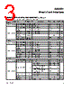
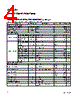
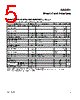

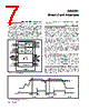

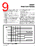


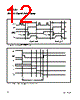
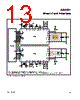

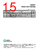

Overall Context:
️· This data pertains to the "DS8024 Smart Card Interface."
️· Values are specified under conditions: VDD = +3.3V, VDDA = +5.0V, TA = +25°C (unless otherwise stated).
️· Many parameters are noted to be "Note 1," "Note 3" indicating supplementary information provided elsewhere in the full datasheet.
1. Power Supply & General Timing
️· VDD: +3.3V
️· VDDA: +5.0V
️· TA (Ambient Temperature): +25°C
️· I/O - I/OIN Falling Edge Delay: ≤ 200 ns
️· Pullup Pulse Active Time: ≥ 100 ns
️· Maximum Frequency (I/O): ≤ 1 MHz
️· Input Capacitance: ≤ 10 pF
2. Data Lines (I/O and I/OIN)
️· Output Low Voltage (Inactive Mode): 0 to 0.3 V (at IOL = 1 mA)
️· Output High Voltage (Active Mode): 0.75 x VCC or VCC (at IOH = ≤ -40μA)
️· Output Rise/Fall Time: ≤ 0.1 μs (at CL = 30 pF)
️· Input Low Voltage: -0.3 to +0.8 V
️· Input High Voltage: 1.5 to VCC
️· Input Low Current: ≤ 700 μA (at VIL = 0V)
️· Input High Current: ≤ 20 μA (at VIH = VCC)
️· Input Rise/Fall Time: ≤ 1.2 μs
️· Current Limitation (Active Mode): ≤ ±15 mA
️· Integrated Pullup Resistor: 9-19 kΩ
️· Current When Pullup Active: -1 mA
3. I/O, AUX1, AUX2 Pins
️· Output Low Voltage (Inactive Mode): 0 to 0.3 V (at IOL = 1 mA)
️· Output High Voltage (Active Mode): 0.75 x VCC or VCC (at IOH = ≤ -40μA)
️· Output Rise/Fall Time: ≤ 0.1 μs (at CL = 30 pF)
️· Input Low Voltage: -0.3 to +0.8 V
️· Input High Voltage: 1.5 to VCC
️· Input Low Current: ≤ 700 μA (at VIL = 0V)
️· Input High Current: ≤ 20 μA (at VIH = VCC)
️· Input Rise/Fall Time: ≤ 1.2 μs
️· Integrated Pullup Resistor: 9-13 kΩ
️· Current When Pullup Active: -1 mA
4. I/OIN, AUX1IN, AUX2IN Pins
️· Output Low Voltage: 0 to 0.3 V
️· Output High Voltage: 0.75 x VCC or VCC
️· Output Rise/Fall Time: ≤ 0.1 μs (at CL = 30 pF)
️· Input Low Voltage: -0.3 to +0.8 V
️· Input High Voltage: 1.5 to VCC
️· Input Low Current: ≤ 700 μA
️· Input High Current: ≤ 20 μA
️· Input Rise/Fall Time: ≤ 1.2 μs
️· Integrated Pullup Resistor: 9-13 kΩ
️· Current When Pullup Active: -1 mA
Important Notes:
️· Consult the Full Datasheet: The "Note 1" and "Note 3" references indicate there is more detailed explanation of these values and conditions that require careful review.
️· Units: Pay close attention to the units (V, μA, kΩ, ns, pF, MHz) for each parameter.
️· Context: Understand the difference between inactive and active modes, as the values often change depending on the operating mode.
Overall Context:
️· This data pertains to the "DS8024 Smart Card Interface."
️· Values are specified under conditions: VDD = +3.3V, VDDA = +5.0V, TA = +25°C (unless otherwise stated).
️· Many parameters are noted to be "Note 1," "Note 3" indicating supplementary information provided elsewhere in the full datasheet.
1. Power Supply & General Timing
️· VDD: +3.3V
️· VDDA: +5.0V
️· TA (Ambient Temperature): +25°C
️· I/O - I/OIN Falling Edge Delay: ≤ 200 ns
️· Pullup Pulse Active Time: ≥ 100 ns
️· Maximum Frequency (I/O): ≤ 1 MHz
️· Input Capacitance: ≤ 10 pF
2. Data Lines (I/O and I/OIN)
️· Output Low Voltage (Inactive Mode): 0 to 0.3 V (at IOL = 1 mA)
️· Output High Voltage (Active Mode): 0.75 x VCC or VCC (at IOH = ≤ -40μA)
️· Output Rise/Fall Time: ≤ 0.1 μs (at CL = 30 pF)
️· Input Low Voltage: -0.3 to +0.8 V
️· Input High Voltage: 1.5 to VCC
️· Input Low Current: ≤ 700 μA (at VIL = 0V)
️· Input High Current: ≤ 20 μA (at VIH = VCC)
️· Input Rise/Fall Time: ≤ 1.2 μs
️· Current Limitation (Active Mode): ≤ ±15 mA
️· Integrated Pullup Resistor: 9-19 kΩ
️· Current When Pullup Active: -1 mA
3. I/O, AUX1, AUX2 Pins
️· Output Low Voltage (Inactive Mode): 0 to 0.3 V (at IOL = 1 mA)
️· Output High Voltage (Active Mode): 0.75 x VCC or VCC (at IOH = ≤ -40μA)
️· Output Rise/Fall Time: ≤ 0.1 μs (at CL = 30 pF)
️· Input Low Voltage: -0.3 to +0.8 V
️· Input High Voltage: 1.5 to VCC
️· Input Low Current: ≤ 700 μA (at VIL = 0V)
️· Input High Current: ≤ 20 μA (at VIH = VCC)
️· Input Rise/Fall Time: ≤ 1.2 μs
️· Integrated Pullup Resistor: 9-13 kΩ
️· Current When Pullup Active: -1 mA
4. I/OIN, AUX1IN, AUX2IN Pins
️· Output Low Voltage: 0 to 0.3 V
️· Output High Voltage: 0.75 x VCC or VCC
️· Output Rise/Fall Time: ≤ 0.1 μs (at CL = 30 pF)
️· Input Low Voltage: -0.3 to +0.8 V
️· Input High Voltage: 1.5 to VCC
️· Input Low Current: ≤ 700 μA
️· Input High Current: ≤ 20 μA
️· Input Rise/Fall Time: ≤ 1.2 μs
️· Integrated Pullup Resistor: 9-13 kΩ
️· Current When Pullup Active: -1 mA
Important Notes:
️· Consult the Full Datasheet: The "Note 1" and "Note 3" references indicate there is more detailed explanation of these values and conditions that require careful review.
️· Units: Pay close attention to the units (V, μA, kΩ, ns, pF, MHz) for each parameter.
️· Context: Understand the difference between inactive and active modes, as the values often change depending on the operating mode.
| Part No. | DS8024-RJX+ |
| Manufacturer | MAXIM |
| Size | 256 Kbytes |
| Pages | 15 pages |
| Description | Smart Card Interface |
| ¿ALLDATASHEET es útil para Ud.? [ DONATE ] |
Todo acerca de Alldatasheet | Publicidad | Contáctenos | Política de Privacidad | Enlace a la hoja de datos | Intercambio de Enlaces | Lista de Fabricantes All Rights Reserved©Alldatasheet.com |
| Russian : Alldatasheetru.com | Korean : Alldatasheet.co.kr | Spanish : Alldatasheet.es | French : Alldatasheet.fr | Italian : Alldatasheetit.com Portuguese : Alldatasheetpt.com | Polish : Alldatasheet.pl | Vietnamese : Alldatasheet.vn Indian : Alldatasheet.in | Mexican : Alldatasheet.com.mx | British : Alldatasheet.co.uk | New Zealand : Alldatasheet.co.nz |
|
Family Site : ic2ic.com |
icmetro.com |
 Spanish ▼
  English
 Chinese
 German
 Japanese
 Russian
 Korean
 French
 Italian
 Portuguese
 Polish
 Vietnamese
 Indian
 Mexican
 British
 New Zealand